Real-time Wi-Fi mobile robot
Remote-controlled car with a two-board architecture: an ESP32-S3 creates the Wi-Fi network and forwards TCP commands over UART to an STM32 running FreeRTOS, which drives the motors and the steering servo and stops on obstacles. Operated from a PyQt5 interface.
Individual final project of Microcontrollers and Power Electronics (UNCuyo, 2025).
- STM32
- C
- ESP32
- ESP-IDF
- FreeRTOS
- PyQt5
- TCP
- UART
- PWM

The project and where it came from
The goal was a vehicle that receives commands from a graphical interface on a PC and executes them in real time: DC motor control, obstacle detection with an ultrasonic sensor, an OLED screen for status, and wireless control over Wi-Fi.
The idea comes from a similar architecture I worked with at ENIB (Brest). I did not have the same hardware, so I redesigned it around what I had: a NUCLEO-F446RE and an ESP32-S3 WROOM. The ESP32 was new to me, so I had to learn ESP-IDF and PlatformIO along the way. It has no industrial purpose; it is a base for mobile robotics and embedded systems.
Architecture: two boards and a PC
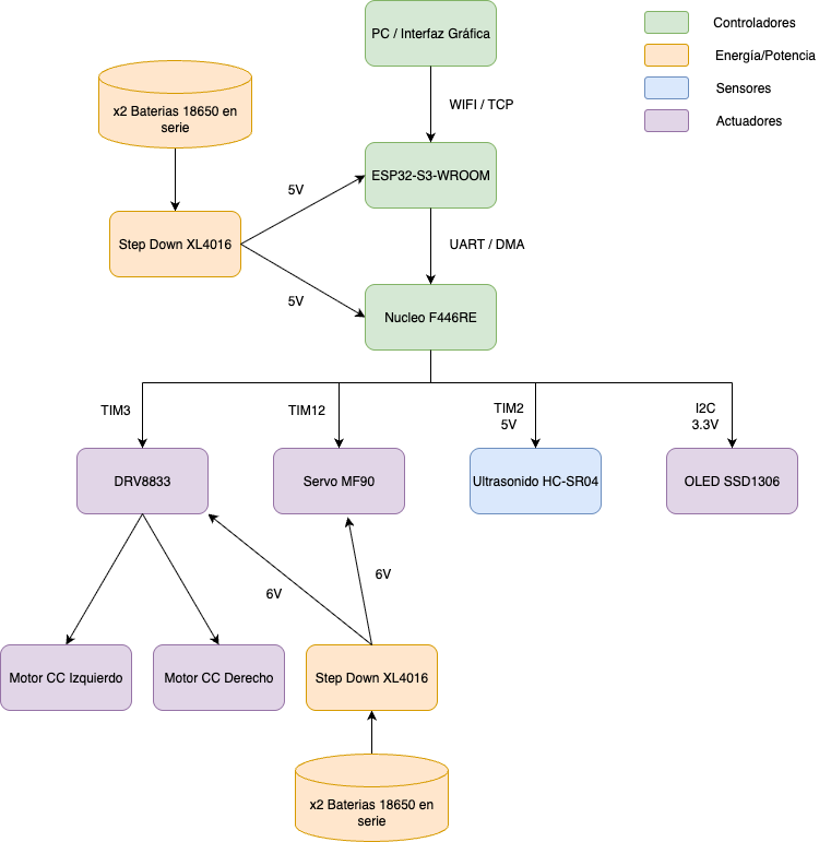
I split the work in two so that real-time control does not compete with networking:
- PC: PyQt5 interface that sends text commands over Wi-Fi/TCP.
- ESP32-S3 (ESP-IDF, FreeRTOS): creates its own Wi-Fi access point, runs a TCP server and forwards each command to the STM32 over UART.
- STM32 NUCLEO-F446RE (FreeRTOS): receives the commands over UART with DMA and drives everything else: TIM3 PWM and GPIO for the DC motors through a DRV8833, TIM12 PWM for the MF90 steering servo, TIM2 to trigger and time the HC-SR04, and I²C for the SSD1306 OLED.
- Power: two banks of two 18650 cells in series and two XL4016 step-down converters, one at 5 V for the NUCLEO and the ESP32 and one at 6 V for the motor driver and the servo.
How it was built
I built it in steps and validated each one before the next:
- Unit tests of each module on its own (ultrasonic sensor, servo, DC motors).
- Basic motion control: motors and servo driven from the NUCLEO with commands typed over UART2, then a simple interface to send them.
- ESP32 integration for Wi-Fi control. Its camera and the many board variants forced me to check pin and power configuration carefully.
- A first camera module with a video panel in the interface and a simple red-object detector that drew a bounding box. I dropped it at the end: it was not tied to the embedded control, so I left it as future work.
- Physical design: a chassis downloaded from Thingiverse and printed at a larger scale. Mounting the parts was the hard part, especially the servo (see the problems section).
- Tests on a fixed stand first and then on the floor, still sending commands over UART from the PC.
- OLED screen, which also put the I²C bus to use.
- Final power integration and complete tests with remote control over Wi-Fi.


STM32 firmware with FreeRTOS
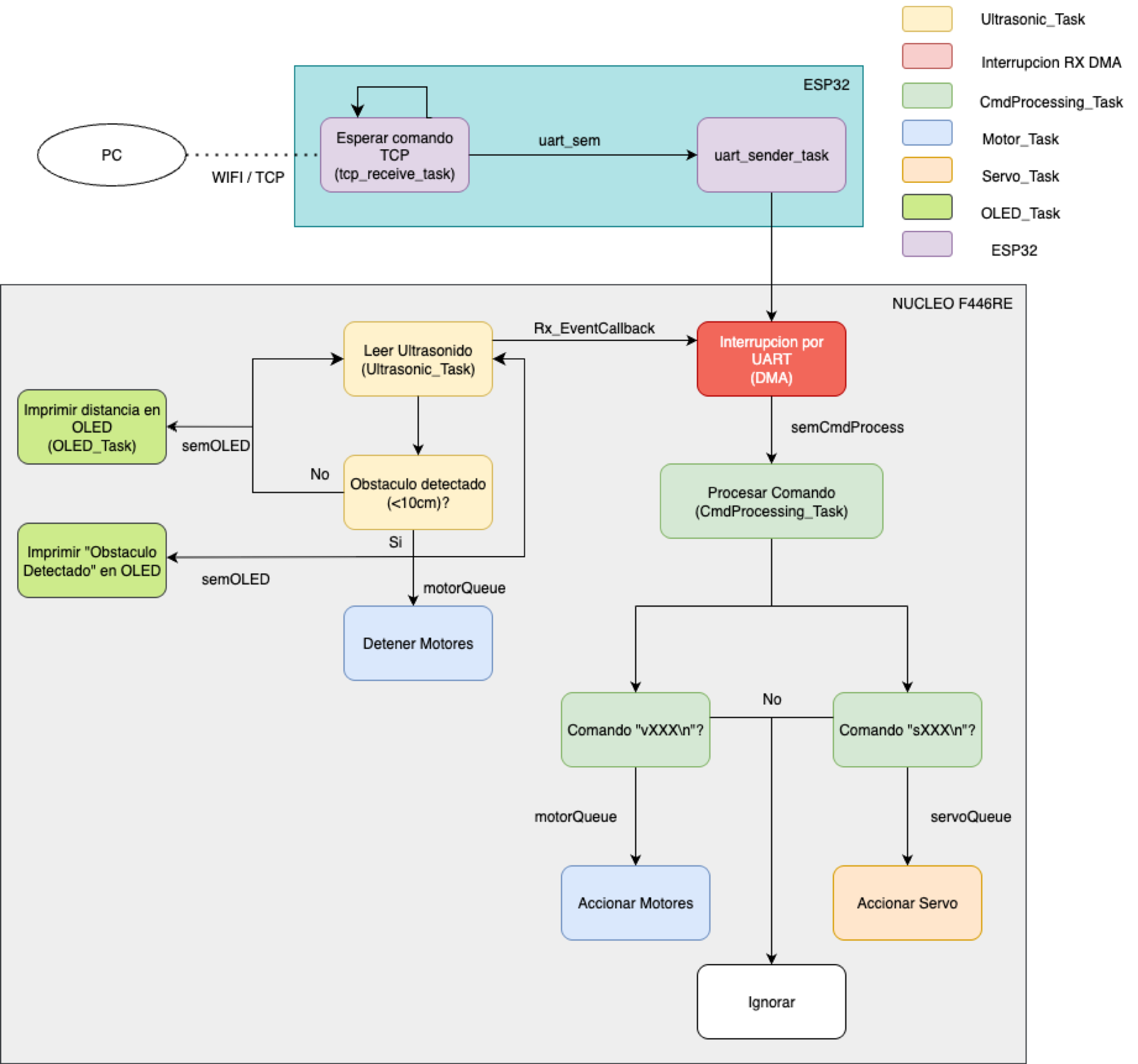
Each function is a task, and interrupts only release semaphores so they stay short:
- Commands arrive on UART2/UART4 (115200 baud) with DMA reception. The callback releases a binary semaphore that wakes CmdProcessing_Task (above normal priority).
- Commands are text lines: vXXX sets speed from −100 to 100 (the sign is the direction) and sXXX sets the servo angle. Anything else is ignored. Valid commands go to the motor or servo queue.
- Motor_Task (normal priority) takes from the motor queue and applies direction and PWM duty. Servo_Task (low) turns the angle into a 1 to 2 ms pulse.
- UltraSonic_Task (high priority, so safety wins): TIM2 emits a 10 µs trigger every 100 ms (about 10 Hz) and two input-capture channels time the echo. If the echo is shorter than 1160 µs (about 20 cm) it sends a stop command to the motor queue.
- OLED_Task (low) shows the distance, or "Obstaculo" when it stops.
The ultrasonic handling is custom, with no external library; the OLED driver is an open-source SSD1306 library.
ESP32 gateway and PC interface
The ESP32 firmware is split in modules: main starts the memory and the UART and launches the Wi-Fi task; wifi_manager sets up the access point; tcp_server listens on port 1234 and starts one receive task per client, which splits the text by line breaks; uart_comm forwards each line to the NUCLEO with a semaphore and a dedicated sender task.
The PC interface is PyQt5 with an internal MVC split (view, controller, model). A serial worker lets me talk to the board directly over UART, which is how I tested before Wi-Fi, and a TCP worker connects to the ESP32 as a client. The interface also has a video panel from the camera attempt.
Demonstration
Teleoperation of the prototype from the PC interface.
Figures
Measured:
- NUCLEO plus peripherals (including OLED and sensor): about 110 mA at 3.3 V with the motors at full speed.
- ESP32: about 52 mA at 5 V, with higher peaks when Wi-Fi starts.
- Whole car at rest, without motors or load: about 100 mA.
Estimated:
- Autonomy: 3 to 4 hours at rest and about 1.5 to 2.5 hours with the motors running.
- Wi-Fi range: 15 to 20 m indoors.
Other design values: HC-SR04 accuracy of ±1 cm from 2 to 200 cm sampled at about 10 Hz; a 200 Ω and 100 Ω divider brings the 5 V echo signal down to about 3.3 V; 470 µF and 100 nF filtering on the 5 V branch, double on the 6 V one, plus 470 µF at the motor driver and at the servo.
Problems and next steps
- Servo: its torque was too low for a firm wheel turn. Fixing it with wire left some slip, and I had trouble matching the servo's natural physical angle to the digital angle for straight driving.
- Power: power problems appeared once I removed the USB cables. I added a second XL4016 and split the circuit into two independent branches, 5 V for logic and 6 V for motors and servo, which made the floor tests stable.
- TCP: sporadic disconnections when many commands are sent in quick succession. It does not stop the car from working, but it is the main thing to fix.
- No encoders: speed is open loop, so there is no PID control.
Next: encoders and PID, a better TCP server on the ESP32, a mobile or web interface, the camera with AI on the video stream, and more sensors for autonomous driving. In a hypothetical commercial version I would swap the HC-SR04 for a VL53L0X laser sensor, use a Raspberry Pi for Wi-Fi and vision, 12 V Pololu motors and a 4S LiPo pack.