Digital audio synthesizer (subtractive)
Monophonic subtractive synthesizer on an STM32F746 Discovery: wavetable oscillator, state-variable filter, ADSR envelope and LFO computed at 44.1 kHz inside the codec interrupt and played from a USB MIDI keyboard.
Academic project (ENIB, 2023).
- STM32F746
- C
- USB MIDI host
- CMSIS-DSP
- WM8994
- SVF
- ADSR
- Wavetable
- Python/SciPy
The goal and the starting point
The goal was a small synthesizer you can play: a USB MIDI keyboard plugged into an STM32F746 Discovery board, and sound coming out of the board's audio codec. The sound is built the subtractive way: an oscillator makes a bright waveform, a filter removes part of it, and an envelope shapes how it starts and fades.
We began from a starter project provided by the course. It already had the board and codec set-up (from the ARM DSP education kit), a USB MIDI host class by Xavier Halgand, a basic oscillator and an almost empty envelope stub. What I wrote is everything that makes it a synthesizer: the oscillator functions, the state-variable filter, the ADSR envelope, the LFO, the MIDI-to-sound mapping and the integration of all of it in the audio interrupt.
Architecture
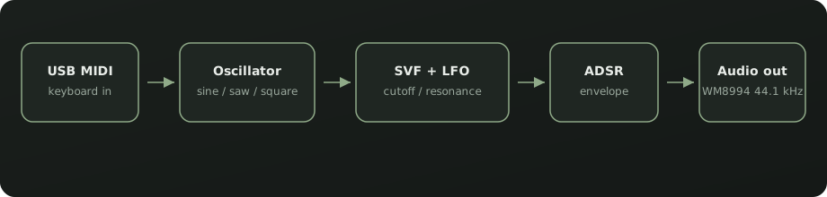
Each audio sample is computed inside the WM8994 codec interrupt at 44.1 kHz on an STM32F746 running at 200 MHz. USB host MIDI packets (note on/off, control change, program change) are parsed in the main loop. Chain: sine (1024-point wavetable), sawtooth or square oscillator; an LFO (about 1 to 20 Hz) added to the filter cutoff; a state-variable filter with cutoff and resonance clamped inside its stability bound; and a linear or exponential ADSR envelope. Left and right outputs carry the same mono sample.
How it was built
The git history of the project shows the order in which it came together:
- First the oscillator functions, rewritten, and the first MIDI handling (note number to frequency).
- Then the state-variable filter, first as new filter files and then working.
- Then the ADSR envelope. The filter worked before the envelope did, because of how the envelope kept track of time; the envelope was finished afterwards.
- Last, the LFO, the control-change mapping that turns the keyboard knobs into parameters, the program changes, and level normalisation of the oscillators.
Prototype in Python, then C
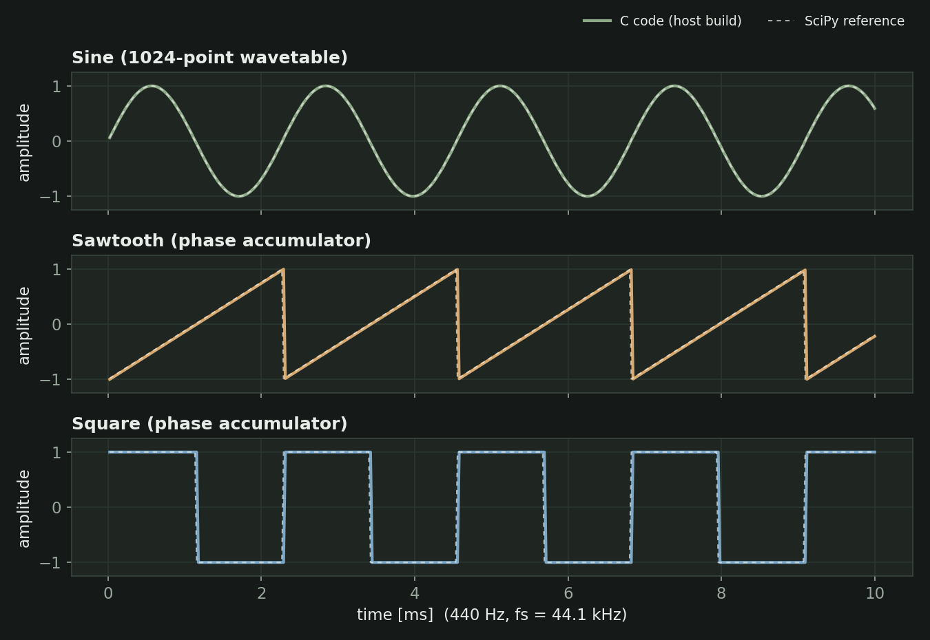
The signals were first worked out on the PC with Python and SciPy. The wavetables (sine, sawtooth, square) were generated in a notebook and pasted into C as arrays. The oscillators were written in C, compiled as a shared library and called from Python with ctypes to compare them with SciPy's reference waveforms. The filter and the envelope were sketched in Python too; for the filter I computed its frequency response with SciPy and worked out its stability limit, which became a clamp on the resonance in the C code. Then everything was rewritten for the board, where the whole chain has to finish inside the audio interrupt.
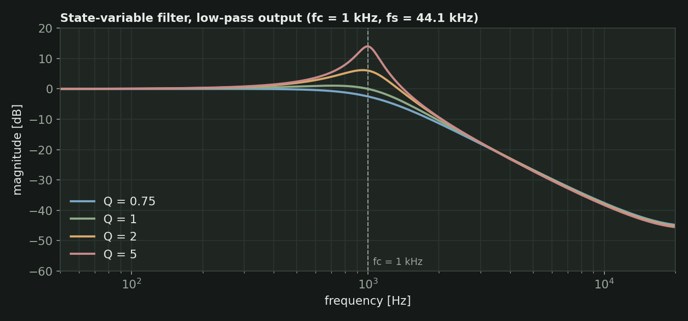
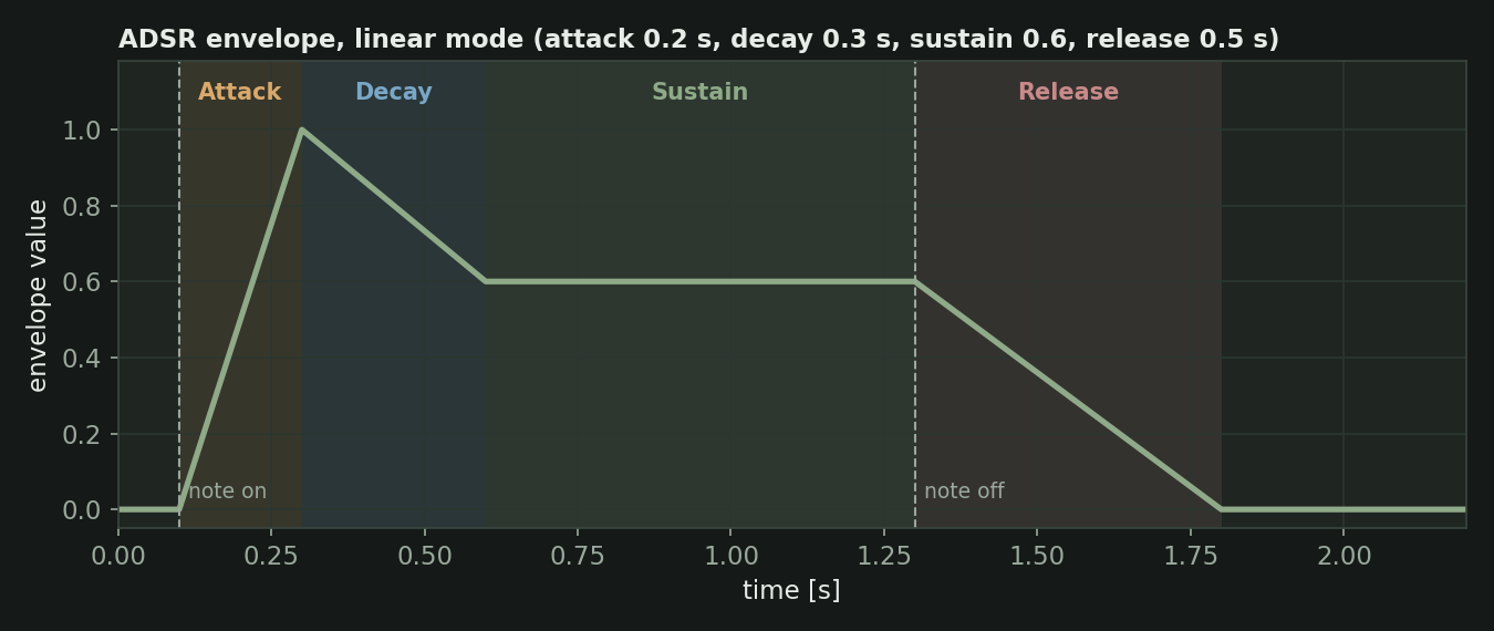
The figures on this page come from compiling the project's own C files on a PC and plotting the output, so they show what the firmware code computes, not what the board played.
The filter
The filter is a state-variable filter with a low-pass, band-pass and high-pass output; the synthesizer uses the low-pass one. It has two coefficients: one from the cutoff frequency and one from the resonance (Q). The filter becomes unstable if the resonance is too low for the cutoff, so the code recomputes a minimum Q every time and never lets Q go below it. From the keyboard, the cutoff goes from 50 Hz to 10 kHz on an exponential scale and Q goes up to 10.
The envelope and the MIDI control
The ADSR is a small state machine updated once per audio sample: idle, attack, decay, sustain and release. The ramp rates are recomputed only when a parameter changes, so the audio interrupt just adds a number per sample. Releasing a key only starts the release if it is the note that is currently playing, so letting go of an old key does not cut the new note.
MIDI notes become frequencies in equal temperament (A4 = 440 Hz). Control changes set the attack (5 ms to 15 s), decay (200 to 500 ms), sustain level (0.001 to 1), release (50 ms to 2 s), filter cutoff, resonance, LFO depth and LFO rate (1 to 20 Hz). Program changes pick the waveform, the envelope mode and whether the LFO is on.
Known issues and scope
A working prototype, not a finished instrument:
- It is monophonic: one note at a time.
- The exponential envelope mode exists in the code but does not work properly: when I ran the code on a PC the envelope jumps to full level instead of ramping. Only the linear mode behaves as intended.
- The LFO adds its output to the filter cutoff on every sample, so the cutoff runs into its limits (50 Hz and 13 kHz) instead of wobbling around the set value. My own notes in the code flag that the cutoff sounds odd with the LFO on, and noise with the sine and the LFO together.
- Glide between notes was planned but not done.
- The audio code is compiled without optimisation.
- FreeRTOS configuration, LCD code, FIR and biquad helpers and a DMA audio variant are in the project tree but are not part of the path that produces sound.